
| Sv translation | ||
|---|---|---|
| ||
NominalwerteNennfrequenz: Die Nennfrequenz wird automatisch ermittelt.
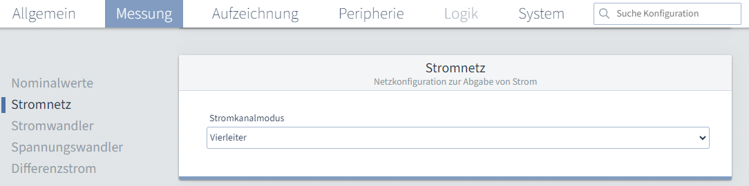
StromnetzStromkanalmodus: Stellen Sie hier die Anschlussvariante ein. Möglich sind folgende Varianten:
StromwandlerStromkanal L1-L3: Stellen Sie das Verhältnis ihrer Stromwandler für die Phasen L1 bis L3 ein. Stromkanal L4: Stellen Sie das Verhältnis ihrer Stromwandler für die Phase L4 ein. Im oberen Bereich können Sie dem Stromkanal L4 einen benutzerdefinierten Namen geben. Dafür können Sie entweder direkt auf den 4. Strommesseingang im Schaubild klicken oder den Haken bei Stromkanal L4 auswählen.
SpannungswandlerHauptmessung L1-L3: Stellen Sie das Verhältnis ihrer Spannungswandler für die Phasen L1 bis L3 ein. Ein Spannungsverhältnis von 400 V primär zu 400 V sekundär bedeutet, dass die Phasen L1-L3 direkt angeschlossen sind.
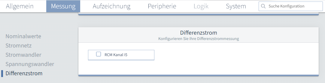
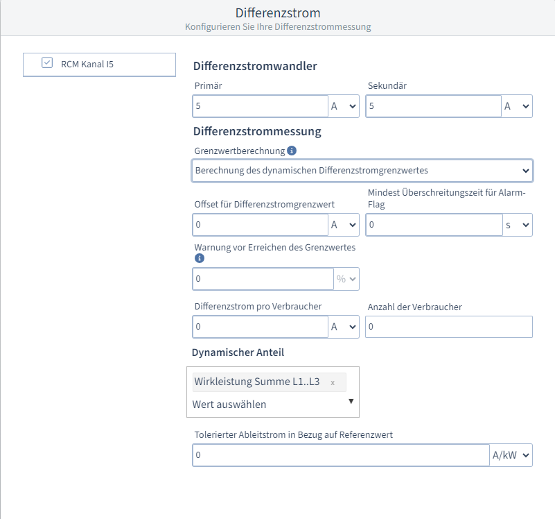
DifferenzstromDifferenzstromwandler: Stellen Sie das Verhältnis ihres Differenzstromwandler ein. Differenzstrommessung: Sie können die Differenzstrommessung entweder abschalten oder zwischen drei Varianten wählen:
Statische Grenzwertberechnung: Beim statischen Differenzstromgrenzwert können Sie einen festen Fehlerstrom in Ampere oder Milliampere eingegeben. Zusätzlich können Sie eine Zeit in Sekunden oder Millisekunden eingeben, die der Fehlerstrom anstehen muss, bevor die Grenzwertverletzung ausgegeben wird. Dabei handelt es sich um die Mindest Überschreitungszeit für Alarm-Flag. Basierend auf diesem Grenzwert kann eine Warnung in Prozent eingestellt werden, die Warnung vor Erreichen des Grenzwertes. Haben Sie beispielsweise einen Grenzwert von 10 A eingestellt und eine Warnung von 80 %, wird die Warnung bei 8 A ausgelöst.
Dynamische Grenzwertberechnung: Warnung und Überschreitungszeit verhalten sich gleich wie bei der statischen Grenzwertberechnung. Sie können unter Dynamischer Anteil einen Referenzwert wählen. Basierend auf dieser Auswahl wird die Einheit des zu tolerierenden Ableitstroms im Bezug auf Referenzwert automatisch gesetzt. Daneben muss der tolerierte Ableitstrom eingetragen werden. Zusammen mit dem Offset für Differenzstromgrenzwert, dem Differenzstrom pro Verbraucher und der Anzahl der Verbraucher ergibt sich folgende Berechnung: Dynamischer Grenzwert = Offset für Differenzstromgrenzwert + (Differenzstrom pro Verbraucher x Anzahl der Verbraucher) + (tolerierenden Ableitstroms im Bezug auf Referenzwert x Referenzwert )
Schrittweise Grenzwertberechnung: Warnung und Überschreitungszeit verhalten sich gleich wie bei der statischen Grenzwertberechnung und beziehen sich auf alle Stufen der nachfolgend zu erstellenden Tabelle.
|


| Sv translation | ||
|---|---|---|
| ||
Nominal valuesNominal frequency: The nominal frequency is determined automatically.
MainsCurrent channel mode: Set the connection variant here. The following variants are possible:
Current transformerCurrent channel L1-L3: Set the ratio of your current transformers for phases L1 to L3. Current channel L4: Set the ratio of your current transformers for phase L4. In the upper area you can give current channel L4 a user-defined name. To do this, you can either click directly on the 4th current measurement input in the diagram or select the check mark for Current channel L4.
Voltage transformerMain measurement L1-L3: Set the ratio of your voltage transformers for phases L1 to L3. A voltage ratio of 400 V primary to 400 V secondary means that phases L1-L3 are directly connected.
Residual currentResidual current transformer: Set the ratio of your residual current transformer. Residual current detection: You can either switch off the residual current measurement or choose between three variants:
Static limit value calculation: With static residual current limit, you can enter a fixed residual current in amperes or milliamperes. You can also enter a time in seconds or milliseconds that the residual current must be present before the limit violation is output. This is the minimum exceedance time for the alarm flag. This limit value can be used to set a warning in percent, which is the warning before the limit value is reached. For example, if you have set a limit value of 10 A and a warning of 80%, the warning will be triggered at 8 A.
Dynamic limit value calculation: The Warning and the Exceedance time behave in the same way as for the Static limit value calculation. You can select a reference value under Dynamic portion. The unit of the leakage current to be tolerated in relation to the reference value is set automatically based on this selection. The tolerated leakage current must be entered next to this. Together with the offset for residual current limit, the residual current per consumer and the number of consumers, the following calculation results: Dynamic limit value = Offset for residual current limit value + (Residual current per consumer xNumber of consumers) + (Tolerated leakage current with respect to reference value x Reference value )
Stepwise limit value calculation:The Warning and Exceedance time behave in the same way as in the static limit value calculation and refer to all levels of the table to be created below.
|


| Sv translation | ||
|---|---|---|
| ||
Valores nominalesFrecuencia nominal: La frecuencia nominal se determina automáticamente.
Red eléctricaModo del canal de corriente: Ajuste aquí la variante de conexión. Las siguientes variantes son posibles:
Transformadores de corrienteCanal de corriente L1-L3: Ajuste la relación de sus transformadores de corriente para las fases L1 hasta L3. Canal de corriente L4: Ajuste la relación de sus transformadores de corriente para la fase L4. En la sección superior podrá dar al canal de corriente L4 un nombre definido por el usuario. A tal efecto podrá o bien hacer directamente clic en la 4.ª entrada de medición de corriente del gráfico o seleccionar la marca de verificación en Canal de corriente L4.
Transformadores de tensiónMedición principal L1-L3: Ajuste la relación de sus transformadores de tensión para las fases L1 hasta L3. Una relación de tensión de 400 V primario a 400 V secundario significa que las fases L1-L3 están conectadas directamente.
Corriente diferencialTransformador de corriente diferencial: Ajuste la relación de su transformador de corriente diferencial. Medición de corriente diferencial: Usted puede desactivar la medición de corriente diferencial o seleccionar entre tres variantes:
Cálculo del valor límite estático: En el valor límite de corriente diferencial estático, usted puede introducir una corriente residual fija en amperios o miliamperios. Adicionalmente, podrá introducir un tiempo en segundos o milisegundos durante el cual debe estar presente la corriente residual antes de que se emita la violación del valor límite. Se trata del Tiempo de superación mínimo para flag de alarma. Sobre la base de este valor límite puede ajustarse una advertencia en porcentaje, la advertencia antes de alcanzarse el valor límite. Si, por ejemplo, ha ajustado un valor límite de 10 A y una advertencia de un 80 %, la advertencia se activa con 8 A.
Cálculo del valor límite dinámico:Advertencia y Tiempo de superación se comportan de la misma manera que en el Cálculo del valor límite estático. Bajo Proporción dinámica podrá seleccionar un Valor de referencia. Sobre la base de esta selección, la unidad de la corriente de fuga que debe tolerarse en relación con el valor de referencia se ajusta automáticamente. Al lado ha de introducirse la corriente de fuga tolerada. Junto con el Offset para el valor límite de corriente diferencial, la Corriente diferencial por consumidor y la Cantidad de consumidores se obtiene el siguiente cálculo: Valor límite dinámico = Offset para el valor límite de corriente diferencial + (Corriente diferencial por consumidor xCantidad de consumidores) + (Corriente de fuga que debe tolerarse en relación con el valor de referencia x Valor de referencia )
Cálculo paso a paso del valor límite:Advertencia y Tiempo de superación se comportan de la misma manera que en el Cálculo del valor límite estático y se refieren a todos los niveles de la tabla que debe crearse a continuación.
|
| Sv translation | ||
|---|---|---|
| ||
Valori nominaliFrequenza nominale: La frequenza nominale viene determinata automaticamente.
Rete elettricaModalità canale di corrente: Impostare qui la variante di collegamento. Sono possibili le seguenti varianti:
Trasformatore di correnteCanale corrente L1-L3: Impostare il rapporto dei trasformatori di corrente per le fasi da L1 a L3. Canale di corrente L4: Impostare il rapporto dei trasformatori di corrente per la fase L4. Nell'area superiore è possibile assegnare al canale corrente L4 un nome definito dall'utente. Per farlo, è possibile cliccare direttamente sull’ingresso corrente 4 nel diagramma oppure selezionare il segno di spunta nel Canale corrente L4.
Trasformatore di tensioneMisurazione principale L1-L3: Impostare il rapporto dei trasformatori di tensione per le fasi da L1 a L3. Un rapporto di tensione di 400 V primario e 400 V secondario significa che le fasi L1-L3 sono collegate direttamente.
Corrente differenzialeTrasformatore di corrente differenziale: Impostare il rapporto del trasformatore di corrente differenziale. Misurazione della corrente differenziale: È possibile disattivare la misurazione della corrente differenziale o scegliere tra tre varianti:
Calcolo del valore limite statico: Con il limite di corrente differenziale statico, è possibile inserire una corrente di guasto fissa in ampere o milliampere. Inoltre, è possibile inserire un tempo in secondi o millisecondi in cui la corrente di guasto deve essere presente prima che venga segnalato il superamento del valore limite. In questo caso si tratta del Tempo minimo di superamento per il flag di allarme. In base a questo valore limite, è possibile impostare un avviso in percentuale, l’Avviso prima del raggiungimento del valore limite. Ad esempio, se si è impostato un valore limite di 10 A e un avviso all'80%, lo stesso scatta a 8 A.
Calcolo del valore limite dinamico:Avviso e Tempo di superamento si comportano allo stesso modo del calcolo del valore limite statico. È possibile selezionare un Valore di riferimentoin Quota dinamica. In base a questa selezione, l'unità della corrente di dispersione da tollerare viene impostata automaticamente rispetto al valore di riferimento. Inoltre, è necessario inserire la corrente di dispersione tollerata. Insieme all’Offset per il valore limite della corrente differenziale, alla Corrente differenziale per utenza e al Numero di utenze risulta il seguente calcolo: Valore limite dinamico = Offset per il valore limite della corrente differenziale + (Corrente differenziale per utenza xNumero di utenze) + (Corrente di dispersione tollerata rispetto al valore di riferimento x Valore di riferimento )
Calcolo del valore limite progressivo:Avviso e Tempo di superamento si comportano allo stesso modo del calcolo del valore limite staticoe fanno riferimento a tutti i livelli della tabella da creare di seguito.
|