
| Sv translation | ||||||
|---|---|---|---|---|---|---|
| ||||||
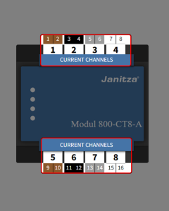
NAVIGATION Nominalwerte Stromnetz → Stromwandler Spannungswandler Differenzstrom Spannungsqualität Wie konfiguriere ich einen Stromkanal für eine Strommessung?Auswahl des Stromkanals aus der Geräteübersicht 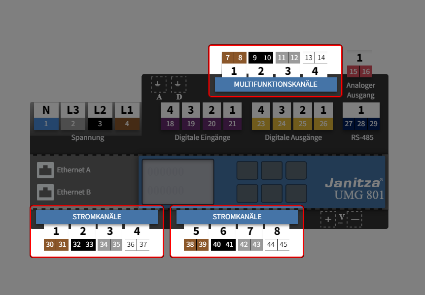 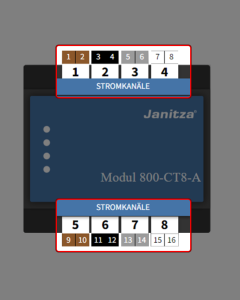 (Zum Vergrößern auf das Vorschaubild klicken) (Zum Vergrößern auf das Vorschaubild klicken)Auf der Geräteübersicht befinden sich farblich gekennzeichnete Schaltflächen zur Konfiguration der Geräteanschlüsse. Diese stellen die einzelnen Kanäle bzw. Messgruppen des Basisgeräts und der Module dar. Klicken Sie auf
Wenn Sie auf die Schaltfläche eines einzelnen Stromkanals im interaktiven Bereich klicken, so öffnet sich gleichzeitig auch der dazugehörige, erweiterte Konfigurationsbereich (unten) oder alternativ
|
| Info | ||
|---|---|---|
| ||
Die Messgruppenmodi haben Einfluss auf die weiteren Einstellmöglichkeiten der einzelnen Strom- und Multifunktionskanäle. Was sind Messgruppenmodi? Siehe Messgruppenmodus |
. Multifunktionskanäle können neben der Strommessung auch zur Differenzstrom- und Temperaturmessung verwendet werden. |
Welche Einstellungen kann ich über den interaktiven Bereich vornehmen?
SCHRITT 2 - 4
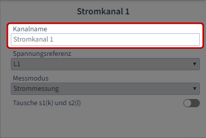
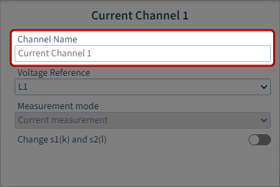
Kanalname vergeben
SCHRITT 3 - 4
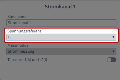
Spannungsreferenz festlegen
SCHRITT 4 - 4
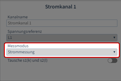
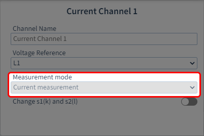
Messmodus festlegen
(Zum Vergrößern auf das Vorschaubild klicken)
(Zum Vergrößern auf das Vorschaubild klicken)
(Zum Vergrößern auf das Vorschaubild klicken)
Schritt 1: Kanalname vergeben
Vergeben Sie zur Identifizierung einen Namen oder eine Bezeichnung.
Schritt 2: Spannungsreferenz festlegen
Abhängig von der Einstellung Messgruppenmodus
.
- Einzelmessung:
Die Spannungsreferenz ist für jeden Kanal in diesem Messgruppenmodus frei parametrierbar.
- Drei-Phasen-
- System (eingeschränkt):
Der 4. Kanal in jeder Gruppe (Stromkanal 4 und 8, Multifunktionskanal 4) kann frei parametriert werden (für bspw. eine Hilfsmessung), wie bei der Einzelmessung.
Für alle anderen Kanäle (1-3/5-7) ist die Spannungsreferenz fest vorgegeben (L1-L2-L3).
Schritt 3: Messmodus festlegen
Abhängig davon, ob es sich hier um einen Strom- oder Multifunktionskanal handelt.
- Stromkanal:
Der 2. Kanal in jeder Gruppe (Stromkanal 2 und 6, Multifunktionskanal 2) ist prametrierbar und verfügt über folgende Messmodi:
Strommessung: Messung über drei Stromwandler
Berechnet: (Aron-Schaltung): Messung über zwei Stromwandler
Für alle anderen Stromkanäle ist als Modus die Strommessung fest vorgegeben.
- Multifunktionskanäle:
Verfügen zusätzlich die Messmodi Differenzstrom- und Temperaturmessung.
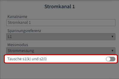
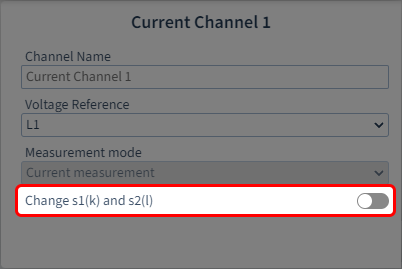
Besonderheiten
Tausche s1(k) und s2(l
(Zum Vergrößern auf das Vorschaubild klicken
)
Wenn die Stromwandler-Anschlüsse bei der Installation falsch angeschlossen wurden, können Sie die Anschlusspolarität über die Software tauschen.
Wie stelle ich die Stromwandlerparameter für die Stromkanäle ein?
Schritt 1
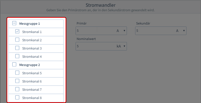
Stromkanäle auswählen
SCHRITT 2 -2
Stromwandlerparameter eingeben
(Zum Vergrößern auf das Vorschaubild klicken)
(Zum Vergrößern auf das Vorschaubild klicken)
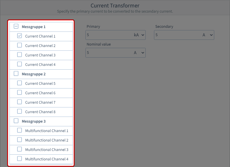
: Stromkanäle auswählen
Wählen Sie zunächst
eine Messgruppe
oder einen
einzelnen Stromkanal
aus. Sie können direkt eine gesamte Messgruppe mit gleichen Parametern versehen oder bei Bedarf jeden Kanal einzeln parametrieren.
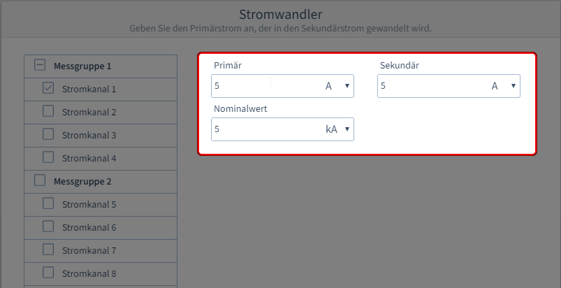
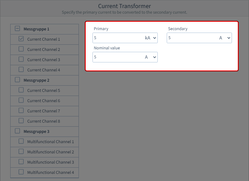
Schritt 2: Stromwandlerparameter eingeben
Tragen Sie den Primär- und Sekundärstrom gemäß den technischen Daten des Spannungswandlers ein. Dieser stellt das Umrechnungs- bzw. Wicklungsverhältnis des Stromwandlers dar.
Den Bemessungsnennstrom des Stromwandlers tragen Sie in das
Eingabefeld Nominalwert
und wählen die passende Einheit. Hierbei handelt es sich um denselben Wert wie im
Eingabefeld Nennstrom auf der
Konfigurationskarte Nominalwerte.
| Sv translation | ||||||
|---|---|---|---|---|---|---|
| ||||||
How do I configure a current channel for a current measurement?Selection of the current channel from the device overview
|

| Info | ||
|---|---|---|
| ||
The measurement group modes have an influence on the further setting options of the individual current and multifunction channels. What are measurement group modes? See |
Multifunction channels can be used for residual current measurement and temperature measurement in addition to current measurement. |
What settings can I make via the interactive area?
STEP 2 - 4
Step 1: Assign channel name
STEP 3 - 4
Specify the voltage reference
STEP 4 - 4
Specify the measuring mode

(Click on the thumbnail to enlarge it)
(Click on the thumbnail to enlarge it)
Assign a name or designation for identification.
Step 2: Specify the voltage reference
Depending on the setting
- Single measurement:
The voltage reference parameters are freely configurable for each channel in this measurement group mode.
- Three-phase
- system (limited):
The 4th channel in each group (current channel 4 and 8, multifunction channel 4) can be configured freely (for example, for an auxiliary measurement), just as for single measurement.
For all other channels (1-3/5-7) the voltage reference is fixed (L1-L2-L3).
Step 3: Specify the measuring mode
Depending on whether this is a current or multifunction channel.
- Current channel:
The 2nd channel in each group (current channel 2 and 6, multifunction channel 2) can be configured and has the following measuring modes:
Current measurement: Measurement using three current transformers
Calculated:(Aron circuit): Measurement using two current transformers
For all other current channels, current measurement is fixed as the mode.
- Multifunction channels:
Also have the measuring modes residual current measurement and temperature measurement.
Special features
Swap s1(k) and s2(l)
If the current transformer connections were incorrectly connected during installation, you can swap the connection polarity via the software.
How do I set the current transformer parameters for the current channels?
Step 1
: Select the current channels
STEP 2 -2
Enter the current transformer parameters
(Click on the thumbnail to enlarge it)
(Click on the thumbnail to enlarge it)
First select
a measurement group
or a
single current channel. You can directly assign the same parameters to an entire measurement group or, if needed, configure each channel individually.
Step 2: Enter the
current transformer parameters
Enter the primary and secondary current
as per the technical data of the voltage transformer. This represents the conversion or winding ratio of the current transformer.
Enter the rated nominal current of the current transformer in
the Nominal value
input field and select the appropriate unit. This is the same value as in
the Nominal
current input field on the configuration
card Nominal values.
![]()
| Sv translation | ||||||
|---|---|---|---|---|---|---|
| ||||||
¿Cómo configuro un canal de corriente para una medición de corriente?Selección del canal de corriente en la vista general de dispositivos  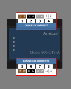 (para ampliar, hacer clic en la imagen de vista previa) (para ampliar, hacer clic en la imagen de vista previa)En la vista general de dispositivos hay unos botones marcados en color para la configuración de las conexiones de los dispositivos. Estos botones representan los diferentes canales o grupos de medición del dispositivo básico y de los módulos. Haga clic en
Si hace clic en el botón de un canal de corriente individual en el área interactiva, al mismo tiempo se abrirá la correspondiente área de configuración avanzada (abajo) o, alternativamente,
|
| Info | ||
|---|---|---|
| ||
Los modos del grupo de medición influyen en las posibilidades de ajuste adicionales de los diferentes canales de corriente y canales multifunción. ¿Qué son los modos del grupo de medición? Véase |
Además de para la medición de corriente, los canales multifunción también pueden utilizarse para la medición de corriente diferencial y para la medición de temperatura. |
¿Qué ajustes puedo realizar a través del área interactiva?
PASO 2 - 4
Paso 1: Asignar el nombre del canal
PASO 3 - 4
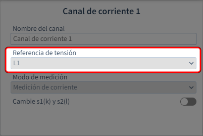
Establecer la referencia de tensión
PASO 4 - 4
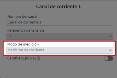
Establecer el modo de medición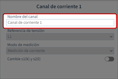
(para ampliar, hacer clic en la imagen de vista previa)
(para ampliar, hacer clic en la imagen de vista previa)
(para ampliar, hacer clic en la imagen de vista previa)
Asigne un nombre o una denominación para la identificación.
Paso 2: Establecer la referencia de tensión
En función del ajuste
- Medición individual:
La referencia de tensión puede parametrizarse libremente para cada canal en este modo del grupo de medición.
- Sistema
- trifásico (con restricciones):
El 4.º canal en cada grupo (canales de corriente 4 y 8, canal multifunción 4) puede parametrizarse libremente (p. ej., para una medición auxiliar), como en la medición individual.
Para todos los demás canales (1-3/5-7), la referencia de tensión está fijamente preestablecida (L1-L2-L3).
Paso 3: Establecer el modo de medición
Dependiendo de si aquí se trata de un canal de corriente o de un canal multifunción.
- Canal de corriente:
El 2.º canal en cada grupo (canales de corriente 2 y 6, canal multifunción 2) puede parametrizarse y dispone de los siguientes modos de medición:
Medición de corriente: medición a través de tres transformadores de corriente
Calculado: (Circuito Aron): medición a través de dos transformadores de corriente
Para todos los demás canales de corriente, como modo está fijamente preestablecida la medición de corriente.
- Canales multifunción:
Adicionalmente disponen de los modos de medición “Medición de corriente diferencial” y “Medición de temperatura”.
Particularidades
Cambiar s1(k) y s2(l
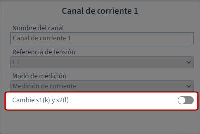
(para ampliar, hacer clic en la imagen de vista previa
)
Si durante la instalación se conectaron incorrectamente las conexiones de los transformadores de corriente, usted podrá cambiar la polaridad de conexión a través del software.
¿Cómo ajusto los parámetros de los transformadores de corriente para los canales de corriente?
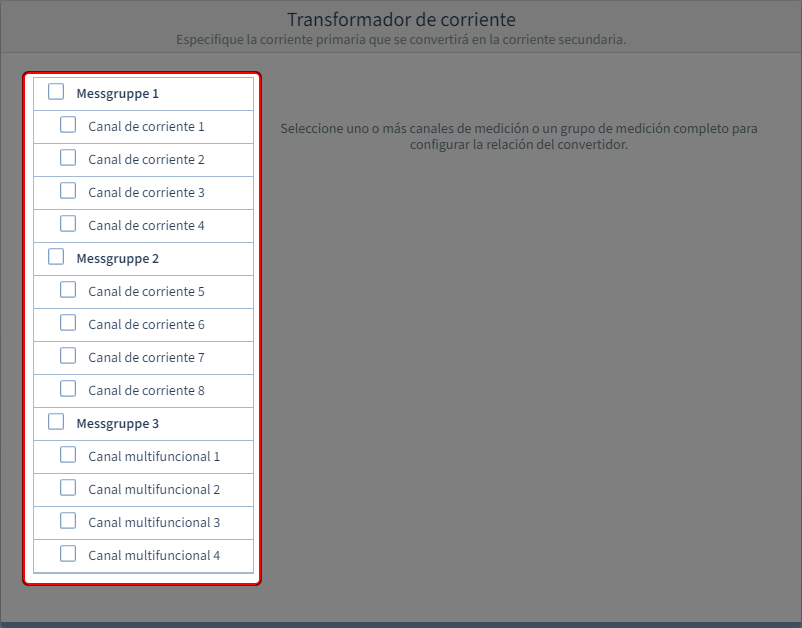
Paso 1
: Seleccionar los canales
PASO 2 - 2
Introducir los parámetros de los transformadoresde corriente
(para ampliar, hacer clic en la imagen de vista previa)

(para ampliar, hacer clic en la imagen de vista previa)
Seleccione en primer lugar
un grupo de medición
o un canal de corriente
individual. Usted puede proveer directamente un grupo de medición completo de los mismos parámetros o, en caso necesario, parametrizar individualmente cada canal.
Paso 2: Introducir los parámetros de los transformadores de corriente
Introduzca
la corriente primaria
y la corriente secundaria
de acuerdo con los datos técnicos del transformador de tensión. Esto representa la relación de conversión o la relación de devanados del transformador de corriente.
Introduzca la corriente nominal del transformador de corriente en el campo de
entrada Valor nominal
y seleccione la unidad adecuada. Se trata del mismo valor que en el campo de
entrada Corriente
nominal en la ficha de
configuración Nominalwerte.
![]()
| Sv translation | ||||||
|---|---|---|---|---|---|---|
| ||||||
Come si configura un canale di corrente per una misura di corrente?Selezione del canale di corrente dalla panoramica del dispositivo
|
| Info | ||
|---|---|---|
| ||
Le modalità gruppi di misura influenzano le altre opzioni di impostazione dei singoli canali di corrente e multifunzione. Cosa sono le modalità dei gruppi di misura? Vedere |
I canali multifunzione possono essere utilizzati per la misurazione differenziale della corrente e della temperatura, oltre che per la misurazione della corrente. |
Quali impostazioni è possibile effettuare tramite l’area interattiva?
PASSAGGIO 2 - 4
Passaggio 1: Assegnare il nome del canale
PASSAGGIO 3 - 4
Impostare il riferimento di tensione
PASSAGGIO 4 - 4
Impostare la modalità di misura
(Cliccare sull’immagine di anteprima per ingrandirla)
(Cliccare sull’immagine di anteprima per ingrandirla)
(Cliccare sull’immagine di anteprima per ingrandirla)
Assegnare un nome o una designazione per l’identificazione.
Passaggio 2: Impostare il riferimento di tensione
A seconda dell’impostazione
- Misura singola:
Il riferimento di tensione può essere parametrizzato liberamente per ciascun canale in questa modalità di gruppo di misura.
- Sistema
- trifase (limitato):
Il quarto canale di ciascun gruppo (canale di corrente 4 e 8, canale multifunzione 4) può essere parametrizzato liberamente (ad esempio per una misura ausiliaria), come per la misura individuale.
Per tutti gli altri canali (1-3/5-7) il riferimento di tensione è fisso (L1-L2-L3).
Passaggio 3: Impostare la modalità di misura
A seconda che si tratti di un canale di corrente o multifunzione.
- Canale di corrente:
Il 2° canale di ciascun gruppo (Canali di corrente 2 e 6, canale multifunzione 2) può essere parametrizzato e dispone delle seguenti modalità di misura:
Misurazione corrente: Misura tramite tre trasformatori di corrente
Calcolato: (Inserzione Aron): Misura tramite due trasformatori di corrente
Per tutti gli altri canali di corrente, la modalità di misurazione della corrente è fissa.
- Canali multifunzione:
Inoltre, sono disponibili le modalità di misurazione della corrente residua e della temperatura.
Particolarità
Scambio s1(k) e s2(l
(Cliccare sull’immagine di anteprima per ingrandirla
)
Se i collegamenti del trasformatore di corrente sono stati collegati in modo errato durante l’installazione, è possibile invertirne la polarità tramite il software.
Come si impostano i parametri del trasformatore di corrente per i canali di corrente?
Passaggio 1
: Selezionare i canali della
PASSAGGIO 2 - 2
Inserire i parametri del trasformatore dicorrente
(Cliccare sull’immagine di anteprima per ingrandirla)
(Cliccare sull’immagine di anteprima per ingrandirla)
Selezionare prima
un gruppo di misura
o un
singolo canale di corrente. È possibile assegnare direttamente gli stessi parametri a un intero gruppo di misura o, se necessario, parametrizzare ogni singolo canale.
Passaggio 2: Inserire i parametri del trasformatore di corrente
Inserire la
corrente primaria
e secondaria
in base ai dati tecnici del trasformatore di tensione. Rappresenta il rapporto di conversione o di avvolgimento del trasformatore di corrente.
Inserire la corrente nominale del trasformatore di corrente nel
campo Valore nominale
e selezionare l’unità appropriata. Si tratta dello stesso valore indicato nel
campo Corrente nominale
della scheda di
configurazione Nominalwerte.
![]()