
| Sv translation | |||||||||||
|---|---|---|---|---|---|---|---|---|---|---|---|
| |||||||||||
Einstellungen:
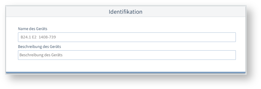
IdentifikationName des GerätsZur eindeutigen Erkennung eines Gerätes geben Sie einen Namen ein (max. 127 Zeichen). Der Name wird in der Kopfzeile des Gerätedisplays und in der Software GridVis® angezeigt. Beschreibung des GerätsFreitextfeld zur näheren Beschreibung der Gerätefunktion, des Standorts, etc. (max. 229 Zeichen). Die Beschreibung wird in der Datenbank gespeichert und nur in der Software GridVis® angezeigt.
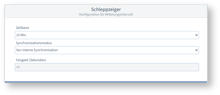
SchleppzeigerDie Schleppzeiger-Funktion erfasst die 3 höchsten Mittelwerte über eine definierte Periodendauer (Zeitbasis). Das Messgerät ermittelt Schleppzeiger für Ströme, Wirk- und Scheinleistungen. ZeitbasisAus den Messwerten über diesen Zeitraum berechnet das Messgerät die Mittelwerte. Die 3 höchsten Mittelwerte werden mit Zeitstempel gespeichert. SynchronisationsmodusDie Synchronisation bestimmt den Startzeitpunkt für die Zeitbasis. Die Synchronisation starten Sie optional über:
Für eine interne Synchronisation muss die Option Synchronisation über Modbus deaktiviert sein! Fangzeit (Sekunden)Die Fangzeit beschreibt das Zeitfenster, in dem ein ankommender Impuls eine Synchronisation des Zeitpunkts vornimmt. Erhält das Gerät einen Impuls außerhalb der Fangzeit, so werden die berechneten Mittelwerte gelöscht und die Zeit zurückgesetzt.
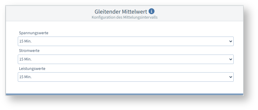
Gleitender MittelwertDas Messgerät erfasst Mittelwerte für die gemessenen Spannungen, Ströme und Leistungen inklusive Zeitstempel. Gleitende Mittelwerte gelten immer für das zuletzt abgelaufene Zeitintervall, ausgehend von der aktuellen Uhrzeit. Die Mittelwerte werden jede Minute neu berechnet. Beispiel: Einstellung 15 min Bei Abfrage der Werte um 10:18 Uhr werden die Mittelwerte für das Intervall 10:03 bis 10:18 gesendet (sekundengenau für die letzten 900 s). SpannungswerteZeitintervall für die Erfassung der Spannungs-Mittelwerte. StromwerteZeitintervall für die Erfassung der Strom-Mittelwerte. LeistungswerteZeitintervall für die Erfassung der Leistungs-Mittelwerte.
Weitere Hinweise:
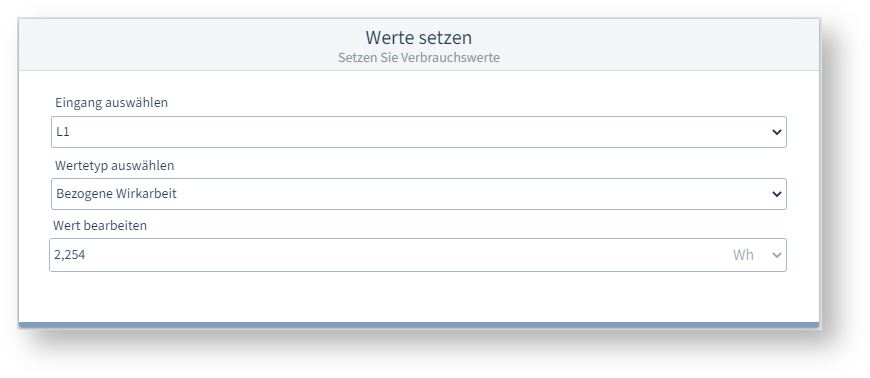
Werte setzenWenn Sie ein Messgerät durch ein neues ersetzen, können Sie hier die letzten Werte des alten Messgeräts als Startwerte für das neue Messgerät setzen. So setzen Sie Verbrauchswerte:
Eingang auswählenWertetyp auswählenWählen Sie in diesen Feldern einen Messwert aus, für den Sie einen Startwert setzen wollen. Wert bearbeitenGeben Sie den an das Messgerät zu übertragenden Startwert an, für den unter Eingang auswählen und Wertetyp auswählen gewählten Messwert. Standardmäßig zeigt dieses Feld den aktuellen Zählerstand im Messgerät an. Daher wird der Zählerstand im Messgerät nicht erhöht, wenn Sie die Konfiguration erneut an das Messgerät übertragen.
|
| Sv translation | |||||||||||
|---|---|---|---|---|---|---|---|---|---|---|---|
| |||||||||||
Settings
IdentificationDevice nameTo uniquely identify a device, enter a name (max. 127 characters). The name is displayed in the header of the device display and in the GridVis® software. Device descriptionFree text field for a more detailed description of the device function, location, etc. (max. 229 characters). The description is stored in the database and only displayed in the GridVis® software. Drag indicatorThe drag indicator function records the 3 highest average values over a defined period (time base). The measurement device determines drag indicators for currents, active and apparent powers. Time baseThe measurement device calculates the average values from the measured values over this period. The 3 highest average values are saved with a time stamp. Synchronization modeThe synchronization determines the start time for the time base. You can optionally start the synchronization via:
For internal synchronization, the option Synchronization via Modbus must be deactivated! Capture time (seconds)The Capture time describes the time window in which an incoming pulse synchronizes the time instant. If the device receives a pulse outside the capture time, the calculated average values are deleted and the time is reset.
Sliding Average ValueThe measurement device records average values for the measured voltages, currents and powers including a time stamp. Moving or sliding averages always apply to the last elapsed time interval, starting from the current time. The average values are recalculated every minute. Example: Setting 15 min When the values are queried at 10:18, the average values for the interval 10:03 to 10:18are sent (accurate to the second for the last 900 s). Voltage valuesTime interval for capturing the average voltage values. Current valuesTime interval for capturing the average current values. Power valuesTime interval for capturing the average power values.
Further notes:
Setting valuesWhen you replace a measurement device with a new one, you can set the last values of the old measurement device as the start values for the new measurement device here. To set consumption values:
Select inputSelect value typeIn these fields, select a measured value for which you want to set a start value. Edit valueSpecify the start value to be transferred to the measurement device for the measured value selected under Select input and Select value type. By default, this field displays the current meter reading in the measurement device. Consequently, the meter reading in the measurement device will not be increased when you retransmit the configuration to the measurement device. |


| Sv translation | |||||||||||
|---|---|---|---|---|---|---|---|---|---|---|---|
| |||||||||||
Ajustes:
Identification (Identificación)Name of device (Nombre del dispositivo)Introduzca un nombre (máx. 127 caracteres) para el reconocimiento inequívoco de un dispositivo. El nombre se muestra en el encabezado de la pantalla del dispositivo y en el software GridVis®. Description of device (Descripción del dispositivo)Campo de texto libre para la descripción más detallada de la función del dispositivo, la ubicación, etc. (máx. 229 caracteres). La descripción se guarda en la base de datos y solo se muestra en el software GridVis®. Drag indicator (Indicador de seguimiento)La función “Indicador de seguimiento” registra los 3 valores medios más altos durante una duración de periodo definida (base de tiempo). El dispositivo de medición determina indicadores de seguimiento para corrientes, potencias activas y potencias aparentes. Interval length (Base de tiempo)El dispositivo de medición calcula los valores medios a partir de los valores de medición durante este periodo de tiempo. Los 3 valores medios más altos se guardan con un registro de fecha y hora. Synchronization mode (Modo de sincronización)La sincronización determina el momento de inicio para la base de tiempo. Podrá iniciar opcionalmente la sincronización:
¡Para una sincronización interna debe estar desactivada la opción Synchronization by Modbus (Sincronización a través de Modbus)! Boundary time (seconds) (Tiempo de captura (segundos))El tiempo de captura describe la ventana de tiempo en la que un impulso entrante sincroniza el momento. Si el dispositivo recibe un impulso fuera del tiempo de captura, se borran los valores medios calculados y se restablece el tiempo.
Sliding Average Value (Valor medio móvil)El dispositivo de medición registra valores medios para las tensiones, corrientes y potencias medidas, registro de fecha y hora inclusive. Los valores medios móviles siempre son válidos para el último intervalo de tiempo transcurrido, partiendo de la hora actual. Los valores medios vuelven a calcularse cada minuto. Ejemplo: Ajuste 15 min. Al consultar los valores a las 10:18 horas se envían los valores medios para el intervalo desde las 10:03 hasta las 10:18 (con una precisión al segundo para los últimos 900 s). Voltage Values (Valores de tensión)Intervalo de tiempo para el registro de los valores medios de tensión. Current Values (Valores de corriente)Intervalo de tiempo para el registro de los valores medios de corriente. Power Values (Valores de potencia)Intervalo de tiempo para el registro de los valores medios de potencia.
Avisos adicionales:
Adjust values (Ajustar valores)Si usted sustituye un dispositivo de medición por uno nuevo, aquí podrá ajustar los últimos valores del dispositivo de medición antiguo como valores iniciales para el dispositivo de medición nuevo. Proceda de la siguiente manera para ajustar los valores de consumo:
Select input (Seleccionar entrada)Select value type (Seleccionar tipo de valor)Seleccione en estos campos un valor de medición para el que desee ajustar un valor inicial. Edit value (Editar valor)Indique el valor inicial que deba transferirse al dispositivo de medición para el valor de medición seleccionado bajo Select input (Seleccionar entrada) y Select value type (Seleccionar tipo de valor). De manera predeterminada, este campo indica la lectura del contador actual en el dispositivo de medición. Por este motivo la lectura del contador en el dispositivo de medición no se incrementa si usted vuelve a transferir la configuración al dispositivo de medición. |
| Sv translation | |||||||||||
|---|---|---|---|---|---|---|---|---|---|---|---|
| |||||||||||
Impostazioni:
IdentificazioneNome del dispositivoPer riconoscere chiaramente un dispositivo, inserire un nome (massimo 127 caratteri). Il nome viene visualizzato nell’intestazione della schermata del dispositivo e nel software GridVis®. Descrizione del dispositivoCampo di testo libero per una descrizione più dettagliata della funzione del dispositivo, della sua ubicazione, ecc. (max. 229 caratteri). La descrizione viene memorizzata nel database e visualizzata solo nel software GridVis®. Indicatore di trascinamentoLa funzione “indicatore di trascinamento” descrive i 3 valori medi più alti in un intervallo prestabilito (base temporale). Lo strumento di misura determina gli indicatori di trascinamento per le correnti, le potenze attive e apparenti. Base di tempoLo strumento di misura calcola i valori medi dalle letture di questo periodo. I 3 valori medi più alti vengono salvati con una marca temporale. Modalità di sincronizzazioneLa sincronizzazione determina l’ora di inizio della base temporale. La sincronizzazione può essere avviata a scelta tramite:
Per la sincronizzazione interna, deve essere disattivata l’opzione Synchronisation by Modbus! Tempo di acquisizione (in secondi)Il tempo di acquisizione descrive una finestra temporale in cui un impulso in arrivo sincronizza il momento. Se il dispositivo riceve un impulso al di fuori del tempo di acquisizione, i valori medi calcolati vengono cancellati e il tempo viene resettato.
Media mobileLo strumento di misura registra i valori medi delle tensioni, delle correnti e delle potenze misurate con marca temporale. Le medie continue si applicano sempre all’ultimo intervallo trascorso, a partire dall’ora corrente. I valori medi vengono ricalcolati ogni minuto. Esempio: Impostazione 15 min Quando i valori vengono richiesti alle 10:18, vengono inviati i valori medi per l’intervallo10:03-10:18(al secondo per gli ultimi 900 s). Valori di tensioneIntervallo di tempo per la registrazione dei valori medi della tensione. Valori di correnteIntervallo di tempo per la registrazione dei valori medi della corrente. Valori di potenzaIntervallo di tempo per la registrazione dei valori medi della potenza.
Altre note:
Impostazione di valoriSe sisostituisce uno strumento di misura con uno nuovo, qui è possibile impostare gli ultimi valori del vecchio strumento come valori iniziali per il nuovo strumento. Per impostare i valori di consumo:
Selezionare l’ingressoSelezionare il tipo di valoreIn questi campi, selezionare una lettura per la quale si desidera impostare un valore iniziale. Modifica valoreSpecificare il valore iniziale da trasmettere allo strumento di misura per le letture selezionate in Seleziona ingresso e Seleziona tipo di valore. Come impostazione predefinita, questo campo mostra la lettura corrente dello strumento di misura. Pertanto, la lettura dello strumento di misura non aumenta quando si ritrasmette la configurazione allo strumento di misura stesso. |